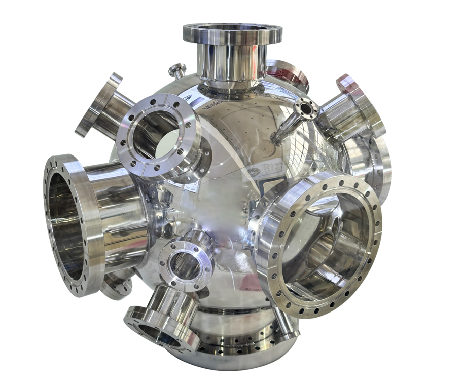

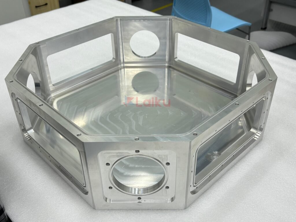
The goal of this guide is not simply to make vacuum chambers cheaper. It is to help you cut down unnecessary cost drivers that do not improve the performance of your custom vacuum chamber.
Since vacuum chambers are high-performance, critical components, we usually feel that if we design one step more precisely, we are further above the safe margin. But at the same time, this over-engineering can significantly increase fabrication costs. Achieving unnecessarily tighter tolerances, higher surface polishes, and deeper vacuum levels can all raise the final vacuum chamber manufacturing cost.
Here are six practical ways to reduce custom vacuum chamber cost without sacrificing the performance metrics.
1. Choose the Vacuum Chamber Material for the Actual Operating Conditions
Raw material costs can range broadly, accounting for around 30% - 60% of the final cost of a vacuum chamber. Over-specifying raw materials is one of the quickest ways to inflate manufacturing costs. So, unless you need strict outgassing control, do not select ultra-premium alloys for non-critical chamber sections.
Table 1: Comparison of Common Vacuum Chamber Material Cost and Applications (Learn more about stainless steel vs. aluminum vacuum chamber cost.)
| Material | Raw Material Cost (Approx. USD/ton) | Relative Machining Cost | Best Use Cases |
|---|---|---|---|
| 6061-T6 Aluminum Alloy | $3,000 - 6,000 | Low | Lightweight chambers, thermal-control applications, semiconductor equipment |
| 304L Austenitic Stainless Steel | $2,300 - 4,000 | Medium | General-purpose HV/UHV chambers, welded process chambers |
| 316L Austenitic Stainless Steel | $3,800 - 5,500 | High | Corrosive process environments, semiconductor and chemical processing |
2. Standardize Flanges, Ports, and Off-the-Shelf Components
Except where you have a necessary requirement for a custom design, always use standard dimensions for your sealing interfaces, viewport steps, and port dimensions. Machining customized, non-standard components require specialized tooling and frequent setup changeovers, which increase both lead times and machining costs.
- ISO-KF (NW10 to NW50) – Suitable for quick-release, low-cost connections in forelines and high-vacuum (HV) applications.
- ISO-K / ISO-F (DN63 to DN630) – A cost-effective choice for larger-diameter connections. Uses elastomer seals with clamp or bolted flange arrangements.
- ConFlat (CF) – Suitable for ultra-high vacuum (UHV) applications and applications requiring high-temperature bakeout sequences (up to 450°C).
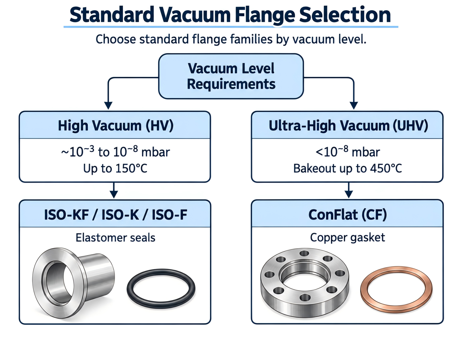
Figure 1: How to Select the Standard Vacuum Flange Based on Vacuum Level
Standardizing avoids plenty of replacement and repair costs in the long-run, because you can easily use readily available parts. They allow you to integrate off-the-shelf viewports, valves, electrical feedthroughs, and shutter mechanisms whenever needed.
3. Optimize Surface Finish and Minimise Polishing Costs
Surface finishing and polishing demand a considerable amount of labor and working hours, which increase the final cost of your vacuum chamber. Therefore, strictly tailor your surface finish requirements to the actual functional needs.
Table 2: Surface Finish Types and Their Cost Impact in Custom Vacuum Chamber Manufacturing
| Surface Finish | Typical Roughness (Ra) | Suitable For | Finishing Cost |
|---|---|---|---|
| Standard Machined (As-Rolled) | Ra 3.2 μm | External, non-vacuum surfaces | Low |
| Fine Machined (Bead Blasted) | Ra 0.8 μm | General HV internal surfaces | Medium |
| Electropolishing | Ra 0.4 μm or better | UHV, cleanliness-sensitive, and low-outgassing applications | High |
Many buyers request high-grade surface finishes like electropolishing across the entire interior and exterior of a vacuum chamber. If you request this simply to stay on the safe side, without any actual operational need, it only adds an unnecessary cost factor.
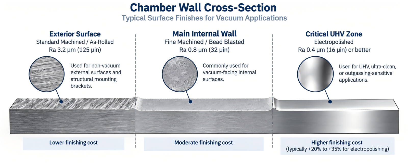
Figure 2: Common Surface Finishes and Their Cost Impact in Vacuum Chamber Manufacturing
4. Simplify Weld Geometries and Eliminate Trapped Volumes
Welded joints in vacuum chambers need to be extremely clean, strong, and continuous to prevent virtual leaks. As manufacturers, we maintain clean working environments and follow strict welding guidelines to produce high-quality chamber welds. So, the welding process takes time and can be costly. However, with proper Design for Manufacturability (DFM) practices, we can minimize many costly vacuum welding mistakes before fabrication begins.
Design Errors That Affect Vacuum Chamber Welding Cost
If your vacuum chamber design contains unnecessarily complex geometries, we need to put a lot more manufacturing effort and time into achieving the required precise welds. As shown in the figure below, these improperly designed joints trap gases. These gases can slowly discharge into the chamber, causing virtual leaks.
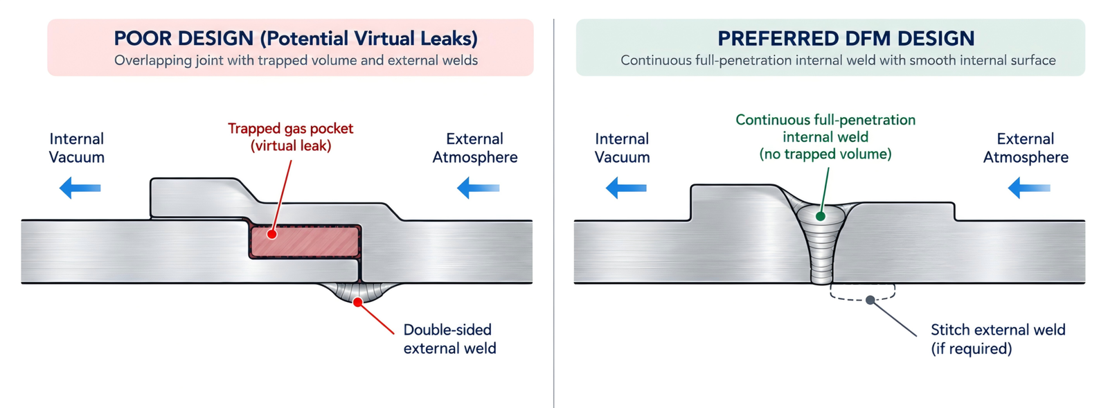
Figure 3: How Trapped Volumes Cause Virtual Leaks in Vacuum Weld Designs
DFM Guidelines for Vacuum Chamber Welding
We recommend incorporating the below guidelines into your vacuum chamber design to minimize welding costs while achieving a high-quality weld:
- Place all primary structural welds on the interior (vacuum side) of the joint. If you need an external weld for strength, use intermittent stitch welding or discontinuous welding (skip-welding) to avoid gas pockets. Otherwise, keeping continuous welds on both sides trap gases and create outgassing surfaces.
- Specify complete joint penetration to eliminate tiny crevices or trapped spaces. Parts must be completely free of grease, cracks, and pores before welding.
- Be careful when specifying standard fasteners. If they don't fit precisely, they can trap air at the bottom of the thread engagement, causing virtual leaks that are difficult to diagnose during helium leak testing.
The best way to avoid common welding errors is to have an early DFM review by the supplier. Aligning your design with their manufacturing strategy and capabilities can reduce many unnecessary costs caused by mismatches between the design and the actual fabrication process.
5. Design for Structural Efficiency to Prevent Deflection
Atmospheric pressure exerts a load of approximately 1.03 kg/cm² (14.7 psi) on the external surface of an evacuated enclosure. On a flat 60 cm × 60 cm chamber door, this translates to more than 3.7 metric tons of compressive force. So, do not underestimate the structural deflection caused by this load. It can lead to bowed sealing faces, misaligned optical stages, and compromised O-ring seals, which can result in costly repairs and frequent replacements.
Given below are some useful structural design optimizations that prevent deflection and add strength to your design:
Use Cylindrical or Spherical Geometries
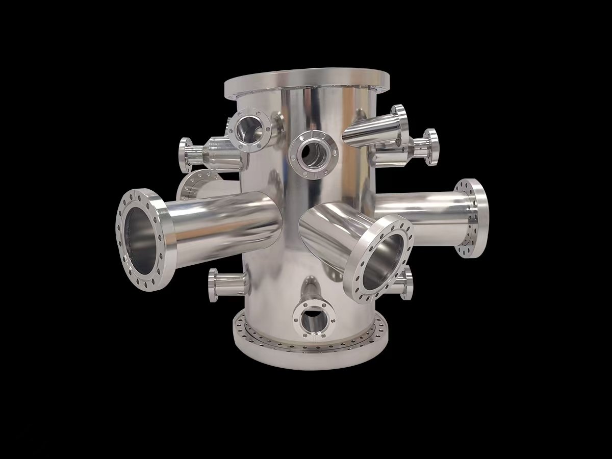
Cylindrical and spherical shapes distribute external pressure more uniformly. They allow you to use thinner wall sections and reduce the overall material weight of the chamber. In most cases, cylindrical and spherical designs are easier to weld than rectangular boxes.
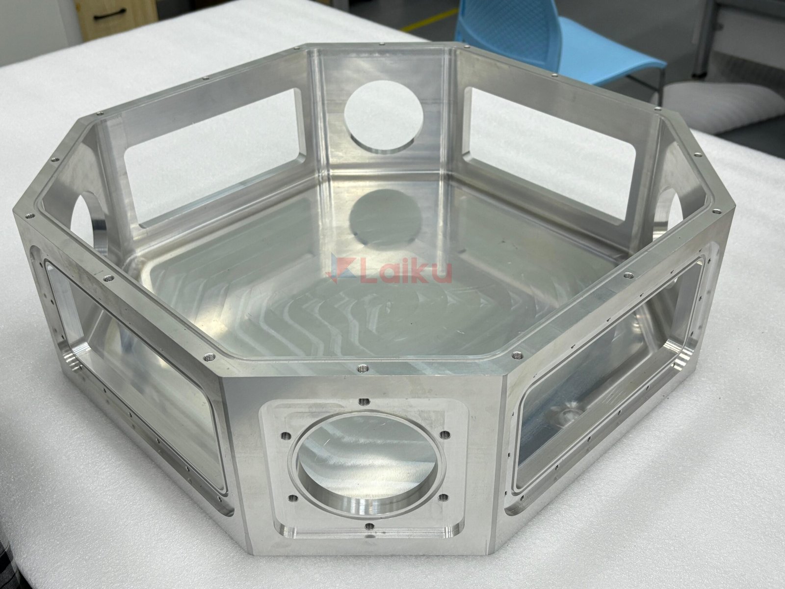
However, there might be certain cases where you need to go with square or rectangular geometries. In such cases, discuss with the supplier and tailor the design to match your application and manufacturing needs.
Use External Reinforcement Ribs
If you're designing rectangular or box chambers to bear heavy loads, do not simply increase the wall thickness to reduce deflection. Thick walls add significant material and weight, yet still experience certain deflection at the center.
To prevent this, use lighter walls together with structural ribs or external stiffeners. They provide more uniform rigidity across the wall and help keep deflection within the allowable design limit. This approach also reduces raw material mass and machining time, lowering the vacuum chamber manufacturing cost.
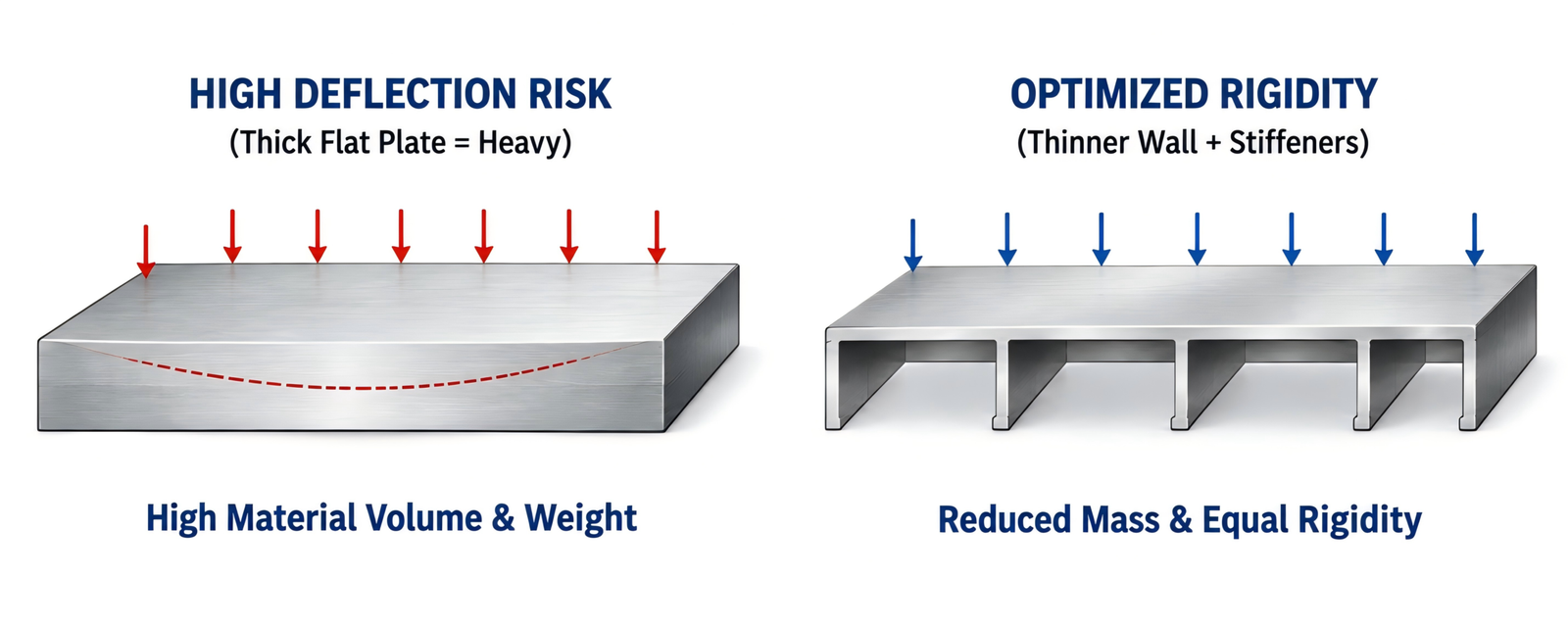
Figure 4: Deflection Comparison of a Thick Flat Wall and a Stiffened Wall Under External Pressure
Optimize Sealing Flange Rigidity
Ensure the flange is thick and rigid enough to prevent warping during welding or under vacuum. If the flange bends or warps, the O-ring will not compress evenly, allowing air to leak into the chamber.
6. Engage Manufacturing Engineers Early and Plan Port Layouts
Sometimes, it might be a set of crowded ports that blocks tool access and adds unnecessary machining complexity to your chamber. Likewise, there can be many design errors that restrict internal tool paths and make the manufacturing process more difficult.
Having a manufacturing engineer review your design early is one of the most effective ways to identify and prevent these costly design errors. They can cross-check your dimensions, layouts, and geometries against the available tooling, machine setups, and CNC machining capabilities and guide you on practical design changes regarding:
- Tooling Access – Keeping sufficient spatial clearance around flange bolt holes for welding torches, cutting tools, clamps, and assembly tools.
- Conductance Pathing – Placing high-vacuum pumping ports with a direct line-of-sight to the main chamber volume. Avoid placing pump inlets behind internal baffles, which restricts gas conductance and requires more expensive pumps to compensate.
- Future-Proofing – Adding 1-2 spare blank ports into the initial build. Adding them during initial CNC machining costs a fraction of what it takes to modify, clean, and re-certify a finished chamber later.
Summary
By systematically applying these six DFM strategies during the initial engineering phase, you can achieve significant cost savings in vacuum chamber manufacturing. Starting with the right material, designing for smoother CNC machining and welding, minimizing structural deflection, standardizing components, and reviewing manufacturability early can all reduce unnecessary cost while still meeting the required high-vacuum and ultra-high-vacuum performance standards.


喷淋电极板-scaled-e1787042008638.jpg)